Orientation

Orientation
Triangle Of Velocities

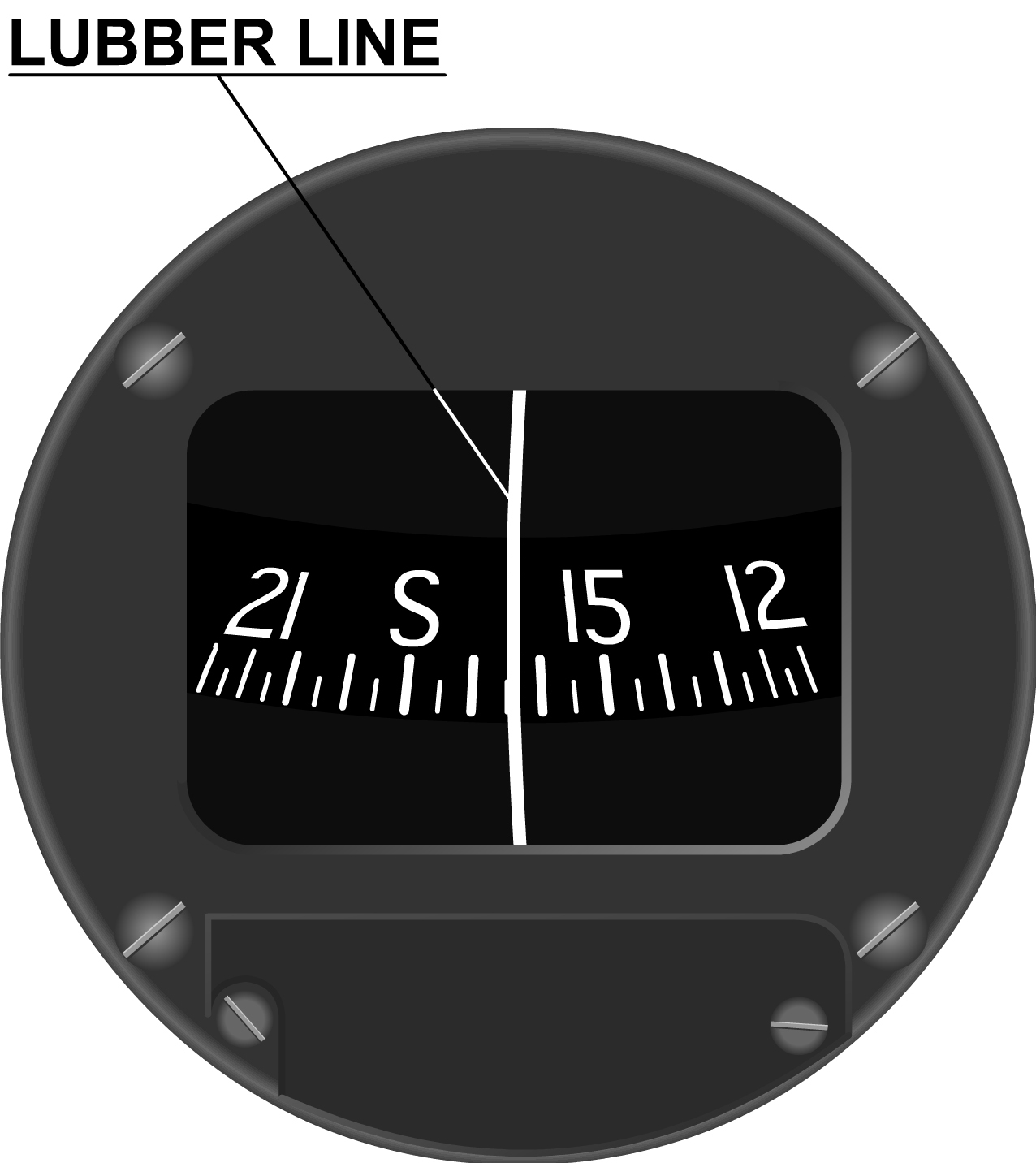
Magnetic Compass, MC


Deviation Card
The deviation table is a list of small deviations that cannot be compensated for by technical means. It is determined by the COMPASS SWING (process of compensating a compass by determining and reducing the deviation coefficients and recording the residual deviations)
Magnetic Compass, MC